This document show you how to fit a Zimo SC68 keep-alive into a loco that has already been fitted with a Zimo sound decoder.
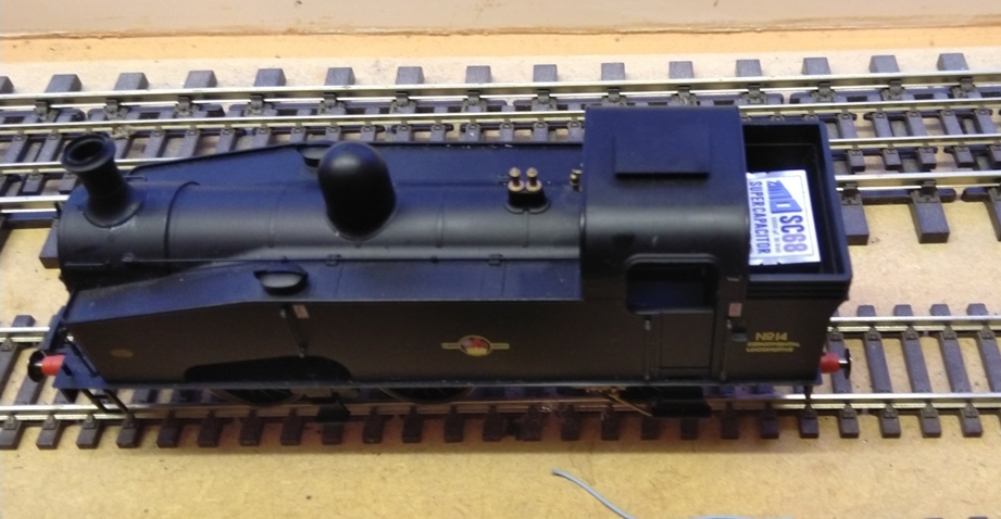
There is very little space available in the Hornby J50 for a sound decoder let alone a decent sized keep-alive. However with a bit work it is possible to fit the Zimo SC68 under the coal load in the bunker.
Dismantle
One thing to be aware of with dismantling the cab and bunker is that some models might have had glue applied and other may not have.
- Remove the body from the chassis, this is down via the 3 screws, 2 at the front, and one at the rear under the coupling.
- Dismantle the cab area, the roof along with the front of the cab need to be removed, the rear of the cab is clipped in, while the front located into the floor of the body and should pull up.
- To remove the rear of the cab it should be possible to push it carefully in the cab and then pull up.
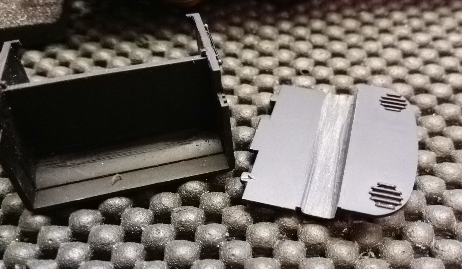
- Finally the bunker can then be removed, by pushing out each side so that is unclips from the main body and push backwards.
Creating Space
The Zimo Keep-alive is just a little bit too big to fit in the bunker as is we need to file away at the back of the cab and the bunker, we need to create approximately 1mm in width and height.
- Using a file carefully thin out the bunker side of the back of the cab from just above the two small cut outs, and just under the ledge
- On the back of the bunker carefully file away some of the back
- Do small amounts of filing at a time, then put the two parts together and test fit the with the sc68 in place, repeat the filing process until there is a tight fit.
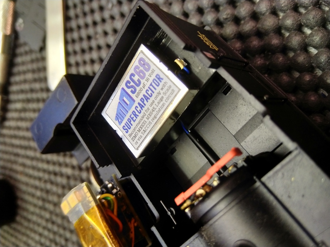
- Once happy that the sc68 will fit, we trimmed the solder tabs and soldered the wires on. We used blue for positive (single tab) and black/white wire for the ground (twin tabs), the wires were approximately 15cm long.
- Locate the sc68 centrally in the bunker and drill a pair of holes through the base and route the wires through it.
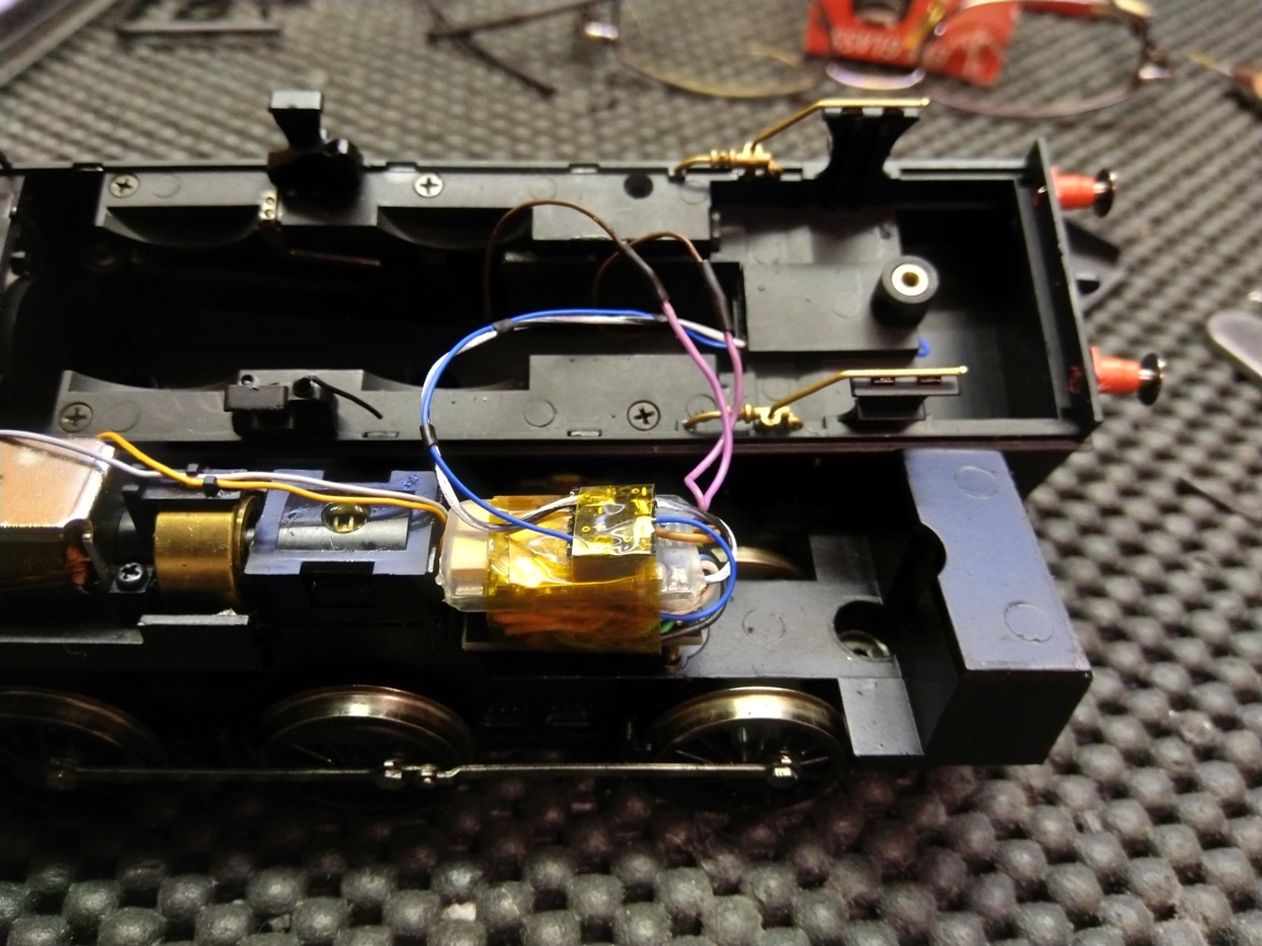
- The wire from the Keep-alive are routed along the floor of the cab, this requires a 1mm hole drilling from the bunker end of the body and through to the firebox end, the wire is thread through a piece of heat-shrink to help hide it away.
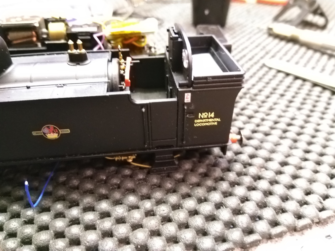
- Route the keep-alive wires through the cab and into the firebox and then refit the bunker into the rear of the body moulding.
- The back of the cab can then be re-fitted, you will need to cut a corner of the cab floor where the cable to the keep-alive runs.
- The 2 wires from the keep-alive are then connected to the Zimo charging circuit SACC16, which in turn is connected to the ground and positive of the Zimo MX648 decoder
- The Body of the loco can then be refitted and tested. Once happy the cab roof can be refitted. The fake coal load in the bunker may need a little bit of trimming on the under side to fit in neatly, again do this with a file until happy.
Fitting the cab back is similar to the removal, push it in at an angle to the floor of the cab, and then push upright.
Disclaimer : Information contained in this document is provided in good faith. Coastal DCC nor any of its employees can be held response for any actions taken as a result of following the information contained within this document. Any alterations are under taken at your own risk and may invalidate the original equipments warranty.
If you do not feel comfortable carrying out these modifications then do not. Download as a pdf